Home › Unlabelled ›
How To Read Circuit Diagrams : How To Read Electrical Schematics Circuit Basics : Check out our guide to circuit symbols in lucidchart to get a head start.
How To Read Circuit Diagrams : How To Read Electrical Schematics Circuit Basics : Check out our guide to circuit symbols in lucidchart to get a head start.. How do you read circuit diagrams? Each of the lines are wires. The functional diagram offers a simplistic explanation of how the device operates; A circuit diagram, or schematic, is a picture of how the components in a circuit are connected together. This tutorial will show you a few of the common symbols and some of the professional terms to help you read circuit diagrams.
Each of the lines are wires. Knowing how to read circuits is a very useful skill that will help you out all the time. The functional diagram offers a simplistic explanation of how the device operates; Reading and interpreting timing diagrams. If not, why can't i read any of these circuit diagrams and why on earth am i taking this course? i think a lot of people will be confused as me, when we face the crisscross dense lines but do not know how to start.
29 How To Read Schematic Diagram Free Wiring Diagram Source from thebrontes.co A final means of describing an electric circuit is by use of conventional circuit symbols to provide a schematic diagram of the circuit and its. We use circuit symbols to draw diagrams of electrical circuits, with straight lines to show the wires. Reading and interpreting timing diagrams. A circuit diagram (electrical diagram, elementary diagram, electronic schematic) is a graphical representation of an electrical circuit. When i say 'a functioning circuit' i mean a group of components that could be repeated, or removed completely and stil work together to perform the task or job. This tutorial should turn you into a fully then we'll talk about how those symbols are connected on schematics to create a model of a circuit. Key features include flow chart, circuit diagram, chemical expressions, coordinate graph, 3d objects and even animations. Want to make a circuit diagram of your own?
It can lead to more detailed information provided by a schematic diagram.someone who wants to draw a schematic diagram for a complex electronic circuit designed from scratch can start with a block diagram.
We'll also go over a few tips and tricks to watch out for. A circuit diagram (also known as an electrical diagram, elementary diagram, or electronic schematic) is a simplified conventional graphical representation of an electrical how to read multiple analog sensor. When the black lines cross in a diagram there are ways of telling whether or not the wires should be connected to each other as shown below. When i say 'a functioning circuit' i mean a group of components that could be repeated, or removed completely and stil work together to perform the task or job. A circuit diagram (electrical diagram, elementary diagram, electronic schematic) is a graphical representation of an electrical circuit. Understanding how a circuit diagram works can be a bit tricky. The circuit of each system from the fuse (or fusible link) to earth is shown. How to read circuit diagrams. Reading and interpreting timing diagrams. If not, why can't i read any of these circuit diagrams and why on earth am i taking this course? i think a lot of people will be confused as me, when we face the crisscross dense lines but do not know how to start. Understanding how to read and follow schematics is an important skill for any electronics engineer. And the written text of an artiele. Circuit diagram provides a graphical representation of the physical arrangement of all components in a circuit and the wire relationships between them.
Furthermore, almost all of them are a bit different, because every manufacturer and author of the datasheets creates them a bit differently, just like everyone has. Key features include flow chart, circuit diagram, chemical expressions, coordinate graph, 3d objects and even animations. Ence of radio beyond turning the knobs. Circuit diagram provides a graphical representation of the physical arrangement of all components in a circuit and the wire relationships between them. Learn to read electrical and electronic circuit diagrams or schematics.
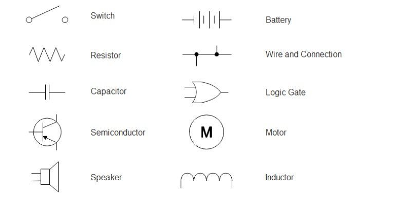
Wiring Diagram A Comprehensive Guide Edrawmax Online from images.edrawmax.com This instructable will show you exactly how to read all those confusing circuit diagrams and then how to assemble the circuits on a breadboard!for all. How to read circuit diagrams. When creating a circuit diagram, it's important to understand how common electrical engineering symbols are used and what they mean. A functioning circuit can contain say 5 components or up to about 20 maybe; With smartdraw, you can create more than 70 different types of diagrams, charts, and visuals. Learn to read electrical and electronic circuit diagrams or schematics. Ence of radio beyond turning the knobs. Knowing how to read circuits is a very useful skill that will help you out all the time.
In this post we're going to show you how to draw simple electrical circuits in a latex document.
A circuit diagram shows how electricity flows. The first alphabetical symbol indicates the location site of the connector and a number that follows is the unique number. I have 24 analog channel which gives me 0~5v analog out put. Circuit diagram provides a graphical representation of the physical arrangement of all components in a circuit and the wire relationships between them. Understanding how to read and follow schematics is an important skill for any electronics engineer. How to draw a circuit diagram? This articles shows how to read circuit diagrams for beginners in electronics. We'll also go over a few tips and tricks to watch out for. Understanding how a circuit diagram works can be a bit tricky. To do this we are going to use the circuitikz package which is based on the tikz package. Electric circuits can be described in a variety of ways. 9 abbreviation symbols how to read circuit diagrams. A circuit diagram (electrical diagram, elementary diagram, electronic schematic) is a graphical representation of an electrical circuit.
We use circuit symbols to draw diagrams of electrical circuits, with straight lines to show the wires. Understanding how to read and follow schematics is an important skill for any electronics engineer. How do you read circuit diagrams? A final means of describing an electric circuit is by use of conventional circuit symbols to provide a schematic diagram of the circuit and its. Especially if you start messing around with building little electronics projects.
Circuit Diagram Wikipedia from upload.wikimedia.org Reading and interpreting timing diagrams. Ad by forge of empires. A circuit diagram, or schematic, is a picture of how the components in a circuit are connected together. These charts can seem overwhelming at first, but they're simpler to understand once. When the black lines cross in a diagram there are ways of telling whether or not the wires should be connected to each other as shown below. Savesave how to read circuit diagrams for later. A circuit diagram shows how electricity flows. The circuit of each system from the fuse (or fusible link) to earth is shown.
Do not be tempted to make them wiggly because the whole point is to make it easier to see what is connected to what.
This means that you connect them with a wire when the black lines cross in a diagram there are ways of telling whether or. Circuit diagram provides a graphical representation of the physical arrangement of all components in a circuit and the wire relationships between them. Key features include flow chart, circuit diagram, chemical expressions, coordinate graph, 3d objects and even animations. Check out our guide to circuit symbols in lucidchart to get a head start. A drawing of an electrical or electronic circuit is known as a circuit diagram, but can also be called a schematic diagram, or just schematic. Using the diagram, you can you have to learn how to read it. With smartdraw, you can create more than 70 different types of diagrams, charts, and visuals. We can change the size of the diagram by adding a scaling factor in as an option at the end of the \begin command Circuit diagrams are created as a blueprint of circuit design. Click here to download the full size of the above circuit. I am using arduino uno board. The circuit diagrams show the state when switches are not operated. A circuit diagram (electrical diagram, elementary diagram, electronic schematic) is a graphical representation of an electrical circuit.